
Modeling a Picnic Table.
In this tutorial I will go through the process of building a picnic table, using fairly basic techniques and tools. The various parts will be made using primitive objects and adjusted using the vertex modeler. The parts will be put together using the basic manipulators and the replicator tool. A simple textures will be applied to the wood parts and screws.
Although I have, of course, seen picnic tables countless times, I had to do some initial research to find out about the shapes and sizes required. I found a design and building instructions for a real table:
http://www.members.shaw.ca/bomr/ptabl.htm
I'm no carpenter, so I have no idea how useful this is for building a real life table, but it was very helpful as a guide for my modeling. I introduced some changes for simplicity but followed most of it.
Apparently a standard 2x6 plank is actually 1.5x5.5 inches (and the 4x2 is 1.5x3.5), so I followed this convention.
Starting
Open a new file: main menu; File>new>empty scene (30ft)
A Basic Plank
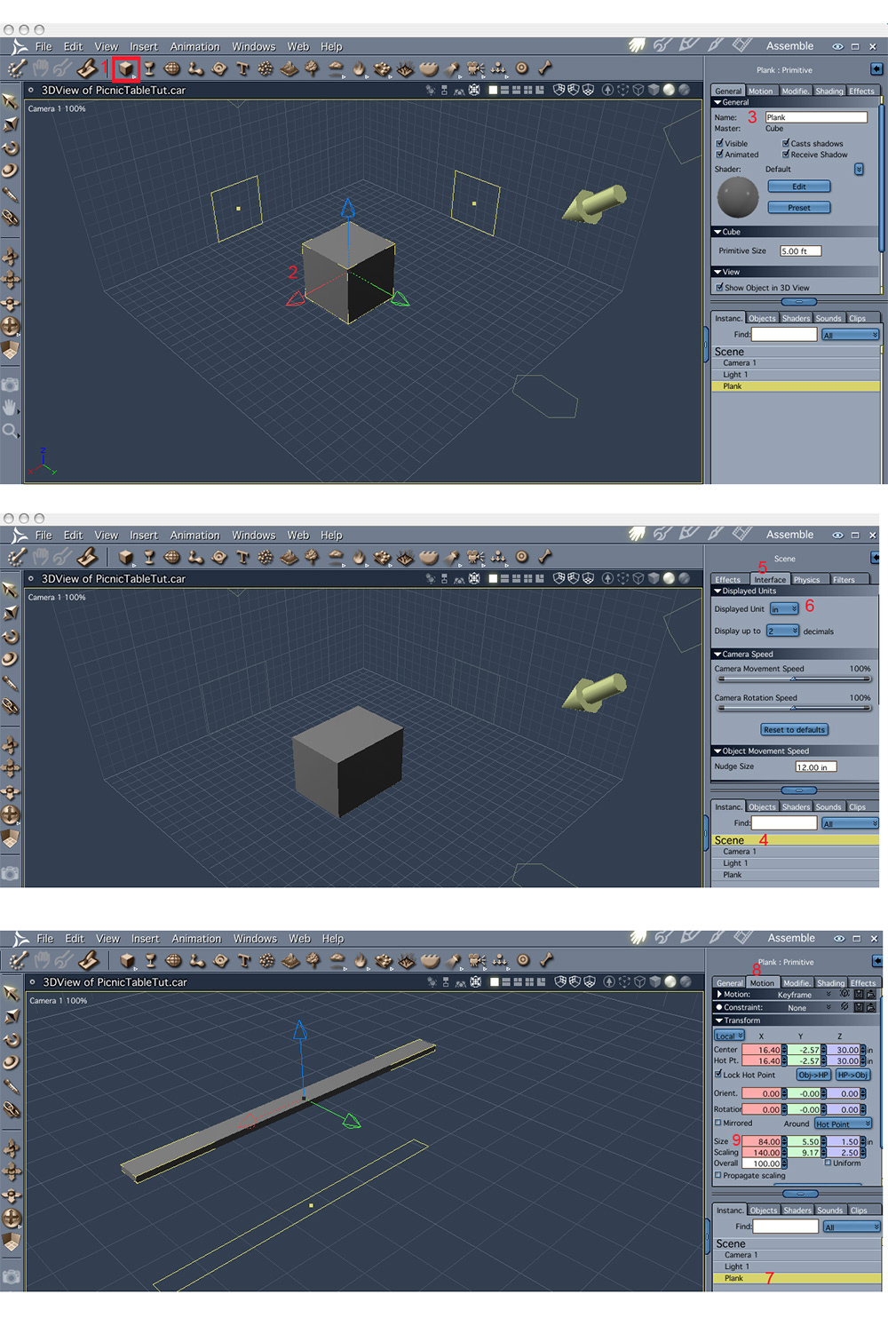
Click
on the primitives modeler and select(click the triangle at the
bottom right of the red square) the cube from the pull down menu.
Drag the cube into the document window and release.
Change the name of the object to 'Plank'. In the motion tab, set the size x=7ft
It is easier to set the y and z size if the units are in inches. Select 'scene' in the properties tray.
Click on the interface tab
Select 'in' as the display units.
Select the plank again in the properties tray.
Select the motion tab
The size in the x dimension is already set from step 3 above(7ft=84inch). Set y and z to 5.5 and 1.5 respectively. (make sure 'uniform' is not selected)
Rounding The Plank's Edges
The planks can be used as constructed above, but they would be nicer with slightly rounded edges. This will give us the opportunity to try out the vertex modeling tool.
1. Convert to vertex modeler
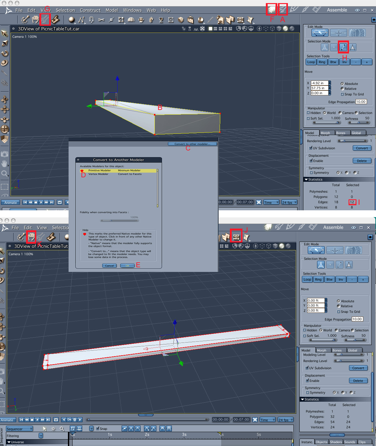
Click on the model room icon(A) or double click on the plank(B) in the 3d window or on its name in the properties tray. You'll get into the model room. Click on 'convert to other modeler'(C) and chose 'vertex modeler'(D), click 'OK' (E). (Don't panic that the object looks like a simple cube rather than a plank). Click on 'assemble room' (F).
(Alternatively use edit> convert to other modeler >vertex modeler.
2. Edit Plank
Click on 'edit vertex object' icon on the left corner (G)– (This allows us to do some modeling but stay in the assemble room in the context of the scene). Chose 'edge selector'(H), select all 6 diagonals by clicking on them while holding down the shift key. Each selected item turns red. Invert the selection by using 'edit>invert selection' from the top menu. All the edges(12) of the plank except the diagonals are now selected. Verify that the selection is correct by checking the number selected in the property tray(I).
Click 'quick fillet' tool (J), click on one of the edges and drag (see arrows for example). This can be refined further but will be enough for a first model.
Click 'finish editing' icon (K).
3. Save the basic plank:
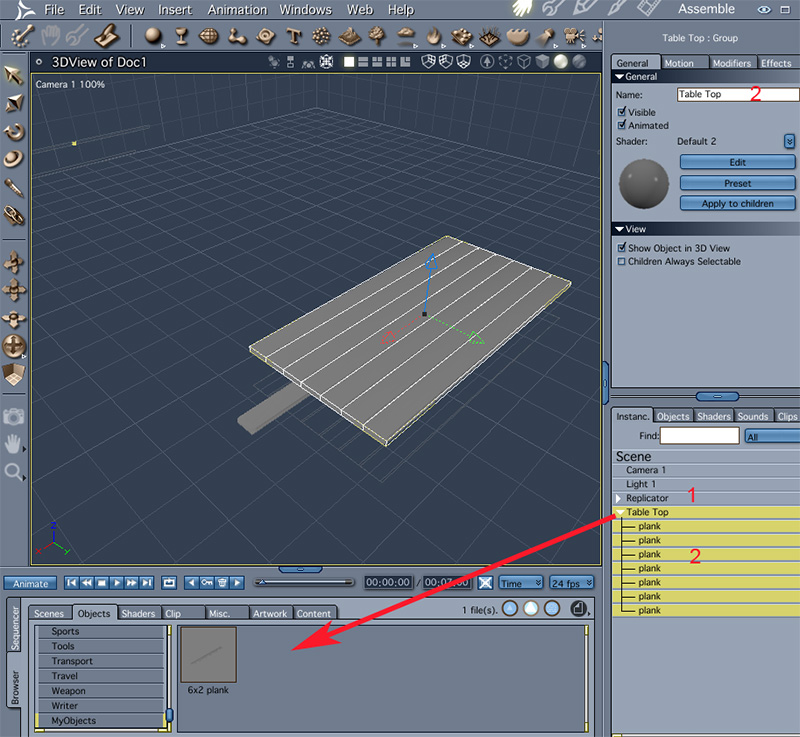
Click on the browser tab on the left of the bottom tray(1); Click on the 'objects' tab(2); select the folder 'MyObjects'(3). Click on the object name, plank, in the properties tray and drag to the browser tray(see arrow). Change the object name and add comments, if you wish, to the Dialog window 'file info' (4).

Making The Table Top
The table top consists of 7 4x6 planks, with a little gap between them. To get this arrangement we can use the replicator tool. First we need to make sure the object we are going to replicate, the plank, is a master object (not just an instance). Click on the plank and then use edit>promote to master.
Now,
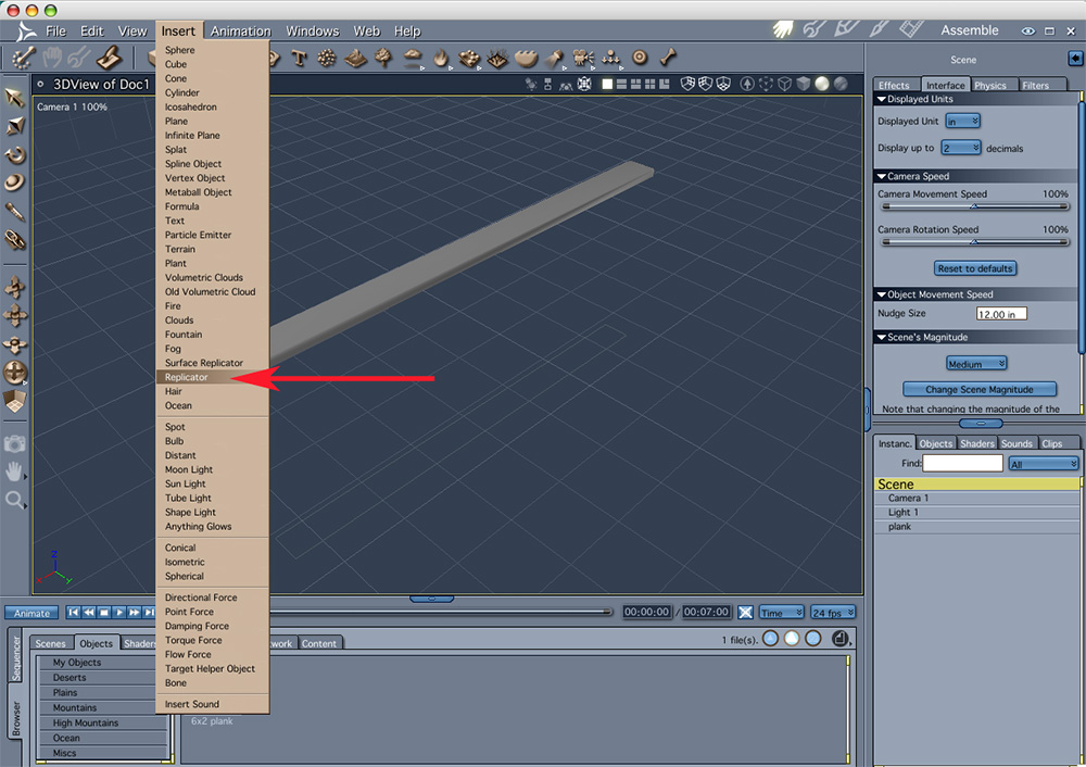
to generate the replicator use insert>replicator in the top menu.
This introduces a new 'object' named replicator, to the scene. To make use of it double click on it(in the 3d window or properties tray), which opens the replicator editor.
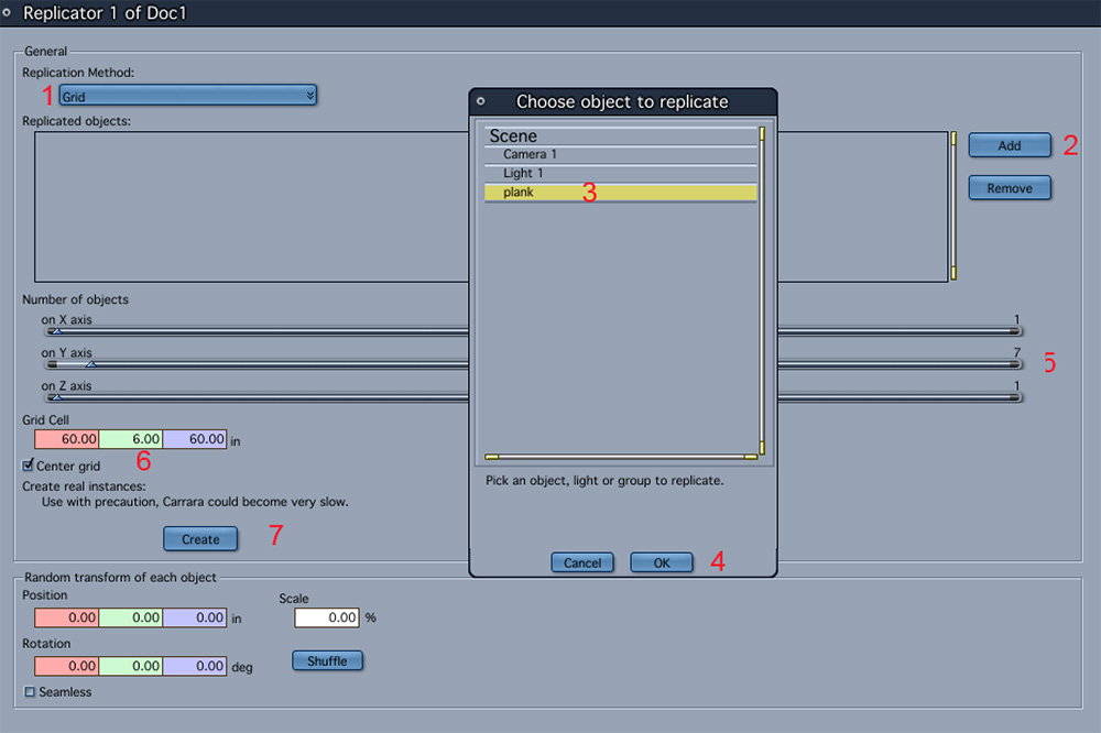
Leave the replicator method as 'grid' (1)
In the 'replicator objects' section click 'add'(2) and chose 'plank'(3) in the 'chose objects to replicate' popup window then click 'OK(4).
In the 'number of objects' section set 1, 7, 1 for x, y and z(5)(using the slider or typing in the values).
We want to replicate the plank only in one dimension, thus, the only relevant grid cell size is in the y direction. Set it to 6”: 5.5” for the plank width plus 0.5” gap (6). We want to create a complete model, which we can export if we so wish, therefore we need to click 'create'(7) in the 'create real instances' section. Confirm 'OK' in the popup window.
Click the 'assemble room' icon.
Delete the original replicator(1), rename converted replicator as 'Table Top'(2).
Save the table top – drag into the desired folder in the browser tray (see arrow)
Making The Seats
Duplicate the table top object (top menu edit>duplicate). Rename new object Seat1.
Delete four planks.
Make outside planks narrower: properties tray, motion tab,y size = 3.5” (1).
Turn on collision detection(2), move planks together by grabbing the move manipulator and moving in the y direction(3, red arrow) till the collision is detected.
Duplicate Seat1 and rename Seat2.
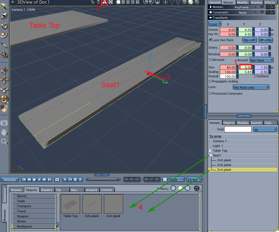
Rename planks '2x4 plank' & '2x6 plank' . Save 2x4 plank and seat1 group (4, green arrows).
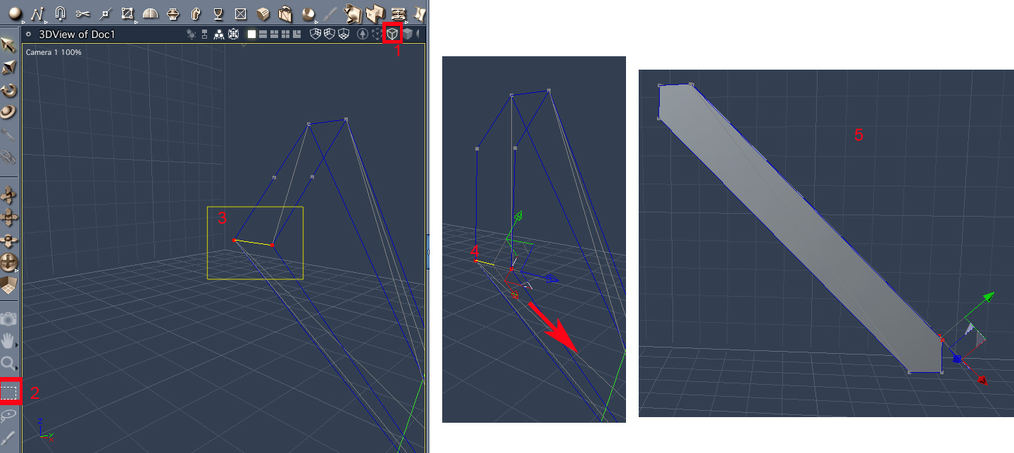
Making The Legs
The legs are made of half a length of a 2x6” plank. They are oriented on a 45 degree diagonal. The corners of the planks are adjusted so that there is a flat contact with the table top, the ground and each other.
Insert cube.
Set units to inches- select 'Scene' in the properties tray then :Interface:Display Units:in
Select the cube, in the general tab change the name to 'leg1' ; in the motion tab set size to 48x5.5x1.5inch and the rotations to 90 45 90
Main menu - edit>convert to other modeler, chose 'vertex modeler' and click OK
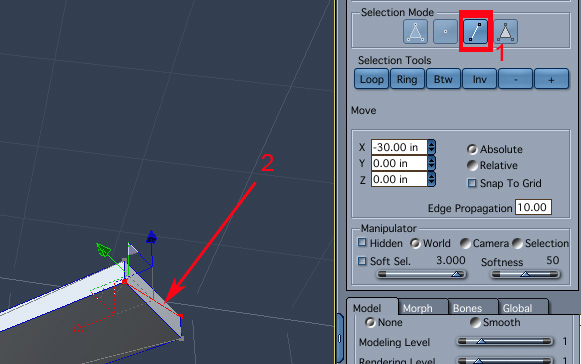
Click 'edit vertex object' icon. Chose selection mode 'edges'(1), click on diagonal of the end face(2). Delete the edge. Same on opposite side.
In the modeler, select tessellate icon(1). Select 'mid-edge to center' (2) then click on the two long edges of the end faces(3).
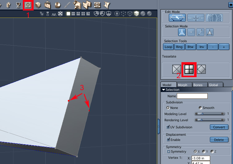
Select wire display (1) (so that all vertices/edges are visible and easy to select).Click on marquee selection icon(2) and enclose the two corner vertices(3). Pull along the edge, till vertical(4). Repeat for other 3 corners(5).
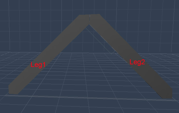
Duplicate the leg (rename duplicate leg2). Activate 'detect collision' and move them together till they touch.
Seat and Table Top Support
The supports are made from 2x4 planks. Their length is slightly less than the items they support – 67” and 40” for the seats and table top, respectively.
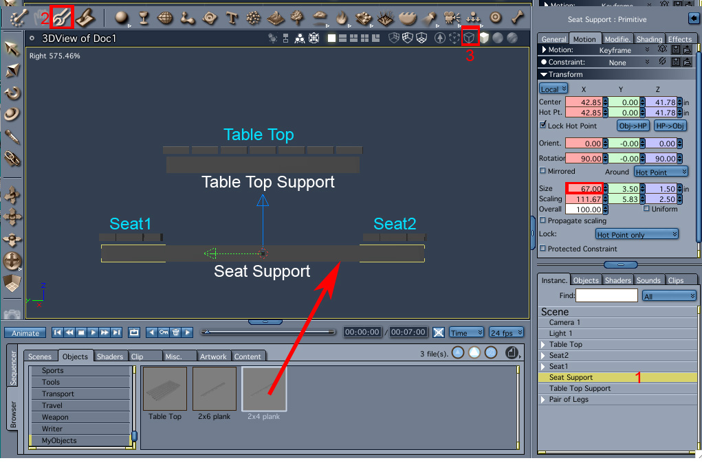
Insert a '2x4 plank' by dragging from the browser tray to the 3d window. Rename 'Seat Support'. Change length to 67” in the motion tab.
Duplicate, rename 'Table Top Support'. Change length to 40”.
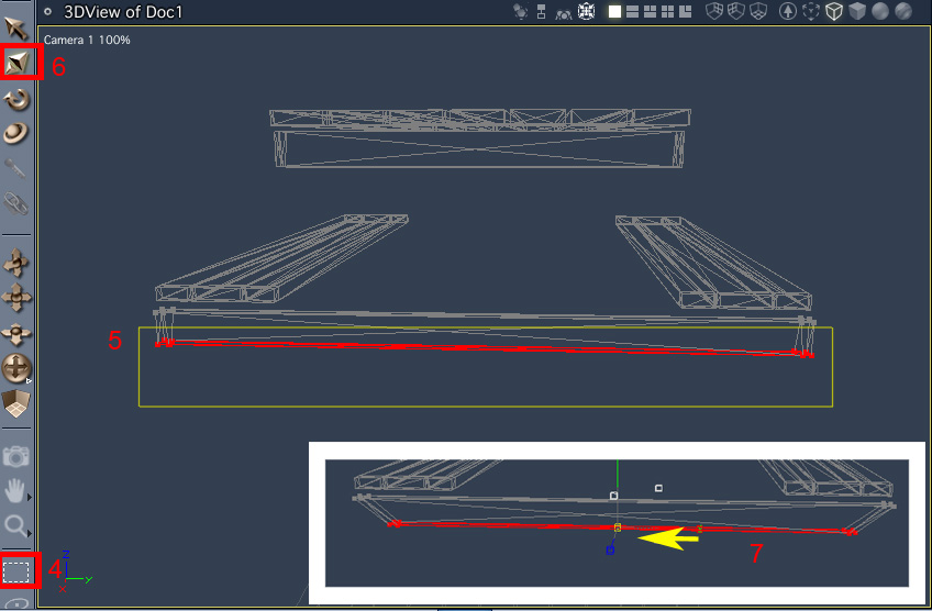
Mitre(slant) the edges:
Select Seat Support(1).
Click on edit vertex object(2). Set create new master in pop up window, click OK.
Chose wire display(3) so we can easily select back edges.
Marquee select bottom edges(4-5).
Select scale manipulator(6), scale down in the y direction(7, yellow arrow).
Click “finish editing” icon.
Repeat for table support.
Assembling the parts.
Leg group:
We will use a pair of legs, 2 seat supports and 2 table top supports to create one leg assembly.
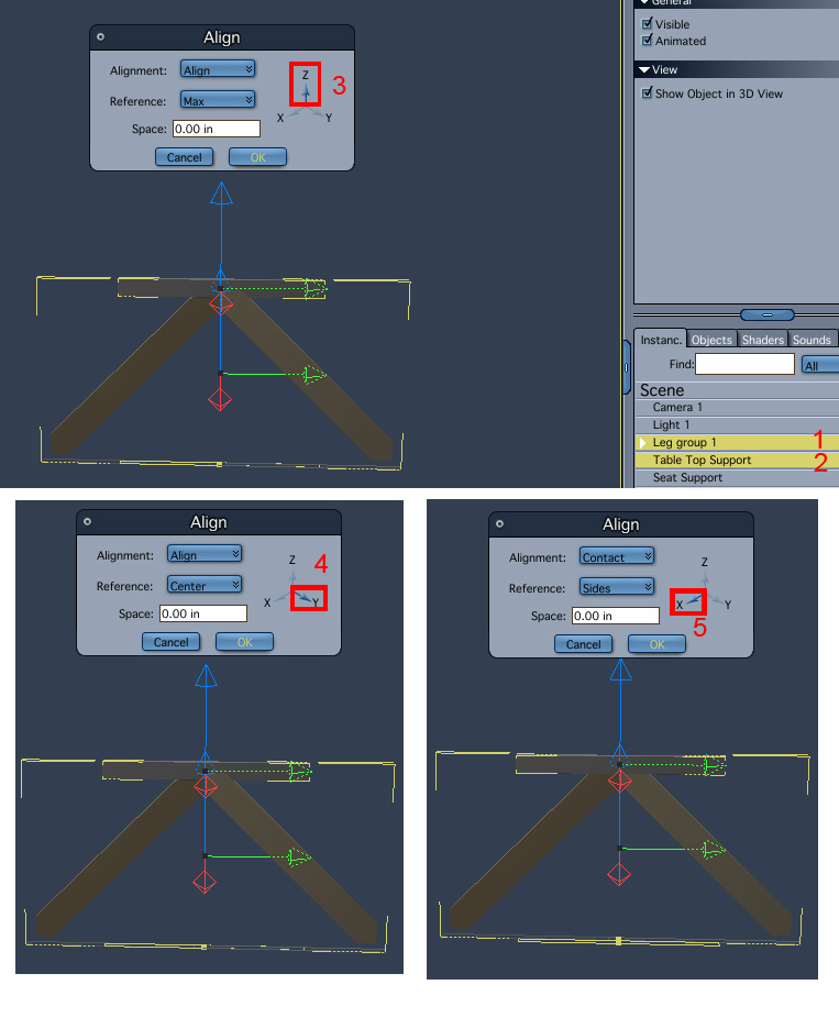
Select the leg group first (this group will stay in a fixed position during the alignment)(1), hold the shift key down and select the table top support(2).
Use the align tool : main menu, edit>align.
First we will align the tops (max value of z) of the two objects. In the popup window(3) chose 'Align'; and 'Max'. On the axes diagram make sure only the z axis is selected, if y is selected by default click on it to deselect. Click on the z axis to select. Click OK.
Use the align tool again to center the 2 objects along the y axis. (4) This time use 'center' as reference and select only the y axis. Click OK
Last, align the objects along x so that the sides of the legs and the support are touching. (5). Use 'contact' for alignment and 'sides' for reference. Make sure only the x axis is selected. Click OK.
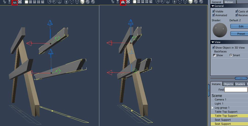
Repeat with the seat support, but for the z direction use center instead of max.
Select both supports. Edit >Duplicate. Ensure collision detection is off. Drag the two new items to the other side of the legs. Turn collision detection on. Move the two items back till they touch the legs.
Include
the 4 supports in the leg group – either by :ungrouping
(edit>ungroup) the leg group, selecting legs and support and
regrouping (edit>group); or by selecting the four supports in the
properties tray and dragging into the group tree.
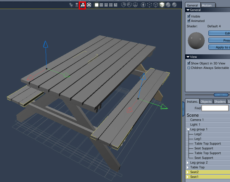
Position table top
Select the leg group then the table top, align centers along the y axis. With collision detection on move the table top down (z) till it touches the leg group.
Move the table top along x so the leg group is near the edge.
Duplicate the leg group, rename and move to other side of the table top along x.
Position seats
Select seat support in leg group 1, then seat1, align max along y.
Select seat support in leg group 1, then seat2, align min along y.
Select table top, then seat1 and seat2, align center along x.
Select the two seats, with collision detection on, move them down (z) till they touch the seat supports.
Adding Screws
The various parts of the table are held together with screws. In this section we will first model a screw head (the screw body isn't visible anywhere and therefore there is no need to model it). The screw heads will then be distributed on the surfaces of the planks in the appropriate positions.
Modeling the screw head.
Insert a sphere to the scene.
Convert the primitive object to a vertex object (edit>convert to other modeler).
Edit vertex object.
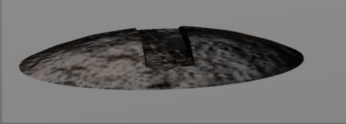
Insert cube(1), use the manipulators to scale and position as in the picture.
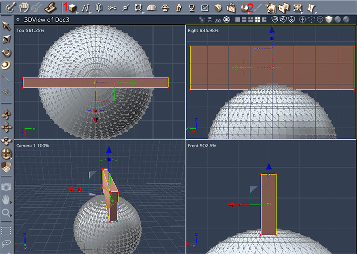
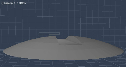
Click on boolean(2) then on the sphere. Type 'return' to finish the operation. The screw head now has the required groove.
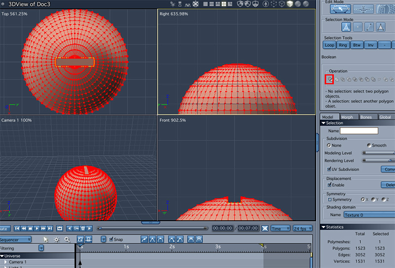
Marque select the bottom part of the sphere, delete. The bottom of the screw head is open, but this will not be seen once positioned on the plank's surface
Finish editing.
Drag to the browser to save.
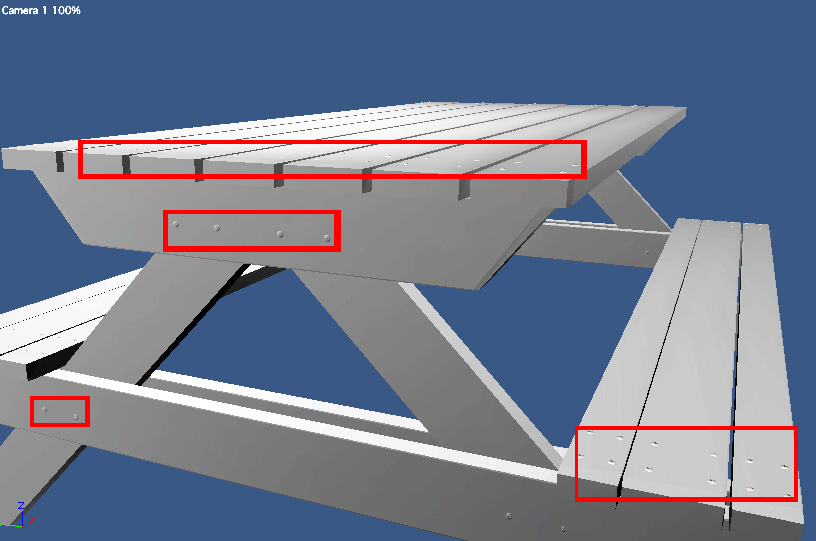
Distributing the screws.
position a screw head on a plank above a table support; duplicate 3 times so there are 4 in total. rename 'plank screw set'.
Insert replicator; edit replicator(double click) add screw set; replicate 2 and 7 times along x and y, at distances of 6.36 and 0.5 feet; create real copies; finish editing;
Align replicator with table top surface.
Similarly add screws to seats and legs.
Adding Texture
The last step in this modeling exercise is applying a shader (also referred to as a material or texture).
For the screws I used a shader provided with the program. The shader for the planks is based on a photograph of a wood surface obtained from the internet.
Screw head:
In the browser tray, shaders tab scroll to the 'metals' folder, select 'iron ingot' and drag to the shader tab in the properties tray.
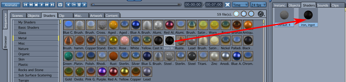
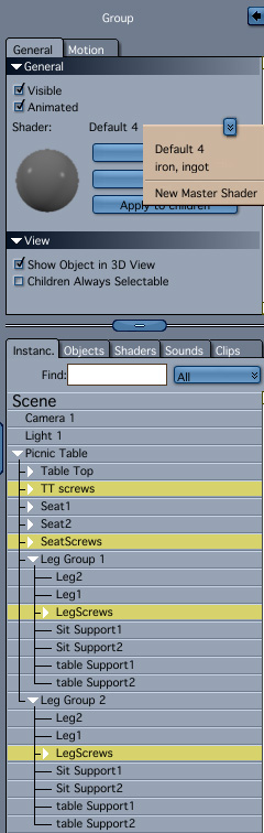
Click
the 'instances' tab in the properties tray. Select all groups of
screws (highlighted). In the shader section at the top of the
properties tray click the double arrow box and chose the 'iron
ingot' shader.
Planks:
The shader of the planks is based on a texture from the site cgtextures.com and is called woodrough0051
I divided it into 4 sections horizontally in a 2d editing application. The resulting size has proportions which would fit around a plank without significant distortion of the texture.
Insert one of our saved untextured planks from the browser tray. In the shader section of the property tray select edit. Select 'Texture Map' from the popup menu of the color channel(1).
Click the 'load' icon and browse to the location of the rough wood pictures(2). Change the filtering option to Gaussian if better quality is required.(3)
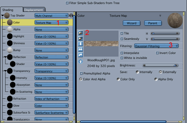
Repeat the procedure for the bump channel too.
Adjust the values in the top shader by moving the sliders or typing in the values.
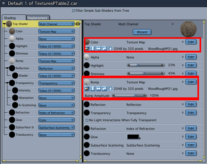
E.g.
adjust the bump amplitude to adjust for smoother or bumpier
surface. Adjust the shininess and highlights if the surface is wet.
Click on the assemble icon to finish editing the textures.
Save the texture by dragging it from the shader tab in the properties tray to the desired folder in the shaders tab of the browser tray
We could apply this texture to all planks, but the repeating pattern would be quite noticeable and unrealistic. Therefore I created several shaders with different texture maps.
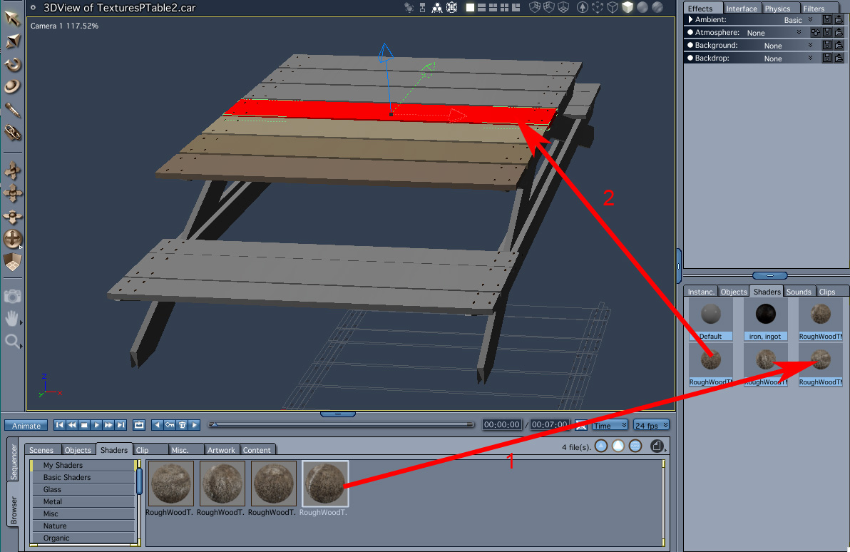
Drag the 4 shaders from the browser tray to the shaders tab in the properties tray(1);
Drag one of the shaders to each plank in the 3d window(2)
Final Model

Please send questions and suggestions to Art.Pearls@yahoo.com